



SP-1500.1 MINI . AMPLIFIER
Pay in easy, interest-free installments with Klarna.
SPAUDIO PERFORMANCE, ITALIAN DESIGN & PASSION
SP-1500.1 MINI
USER MANUAL SP-1500.1 MINI
HIGH-EFFICIENCY CLASS D MONOBLOCK AMPLIFIER 1500W RMS @ 1Ω
ITALIAN DESIGN
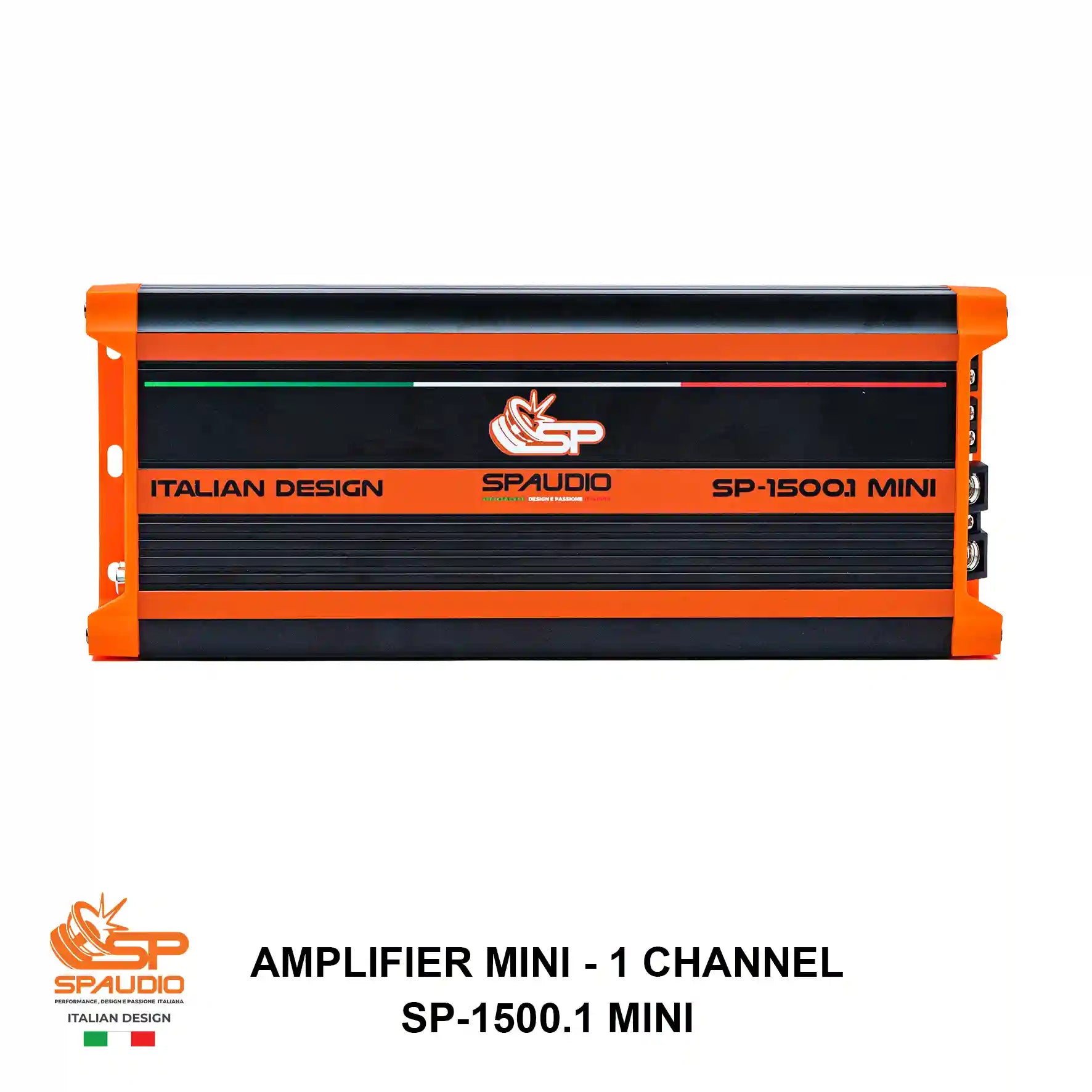
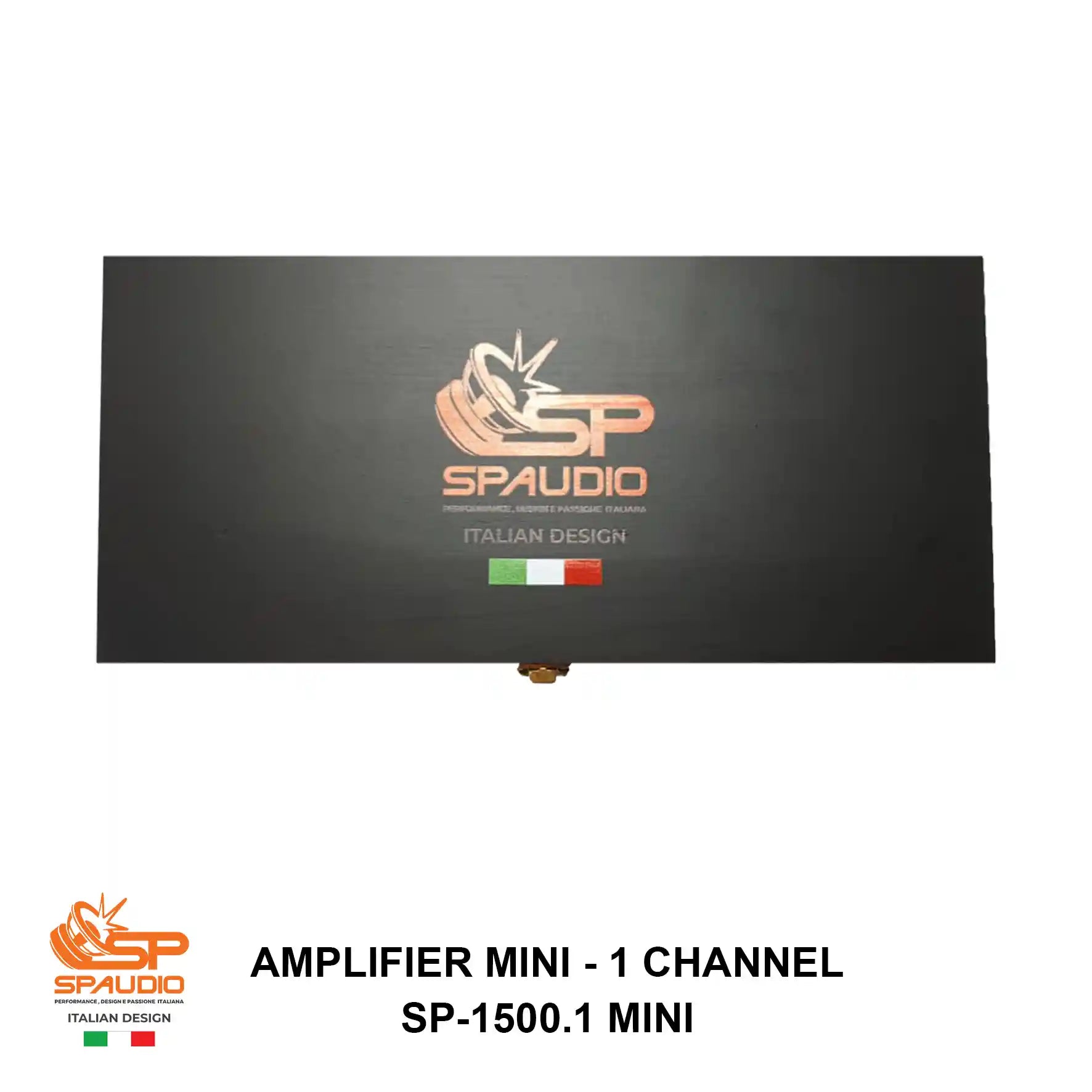
FIGURE 1: SPAUDIO SP-1500.1 MINI
AMPLIFIER MINI-1 CHANNEL SP-1500.1 MINI DISTINCTIVE ITALIAN STYLING WITH SIGNATURE ORANGE SHOCK-ABSORBING RUBBER BUMPERS
1. ACOUSTIC ENGINEERING EXCELLENCE: WHY CHOOSE SP-1500.1 MINI
In professional Car Audio competition and high-fidelity sound reproduction, the ultimate engineering challenge is uniting extreme acoustic output, pristine tonal fidelity, and an ultra-compact mechanical footprint. The SP-1500.1 MINI represents the pinnacle of the Spaudio engineering design philosophy: a no-compromise Class D monoblock amplifier crafted for SPL competitors, low-frequency enthusiasts, and stealth installation professionals.
CLASS D THERMAL EFFICIENCY (>85%)
Leveraging ultra-high-frequency Pulse Width Modulation (PWM) switching architecture, the SP-1500.1 MINI achieves superior energy efficiency exceeding 85%. Unlike conventional Class AB amplifiers that waste massive amounts of battery power as heat, nearly all electrical energy drawn from your electrical system is converted into raw, unadulterated acoustic power, minimizing thermal dissipation and alternator strain.
SMD & DOUBLE-LAYER PCB TECHNOLOGY
Built upon an audiophile-grade 2-layer fiberglass (FR-4) Printed Circuit Board utilizing military-spec Surface Mount Devices (SMD), internal signal paths are exceptionally short. This drastically reduces electromagnetic interference (EMI), enhances structural immunity to severe vehicle vibrations, and guarantees rock-solid stability even under brutal, continuous SPL loads.
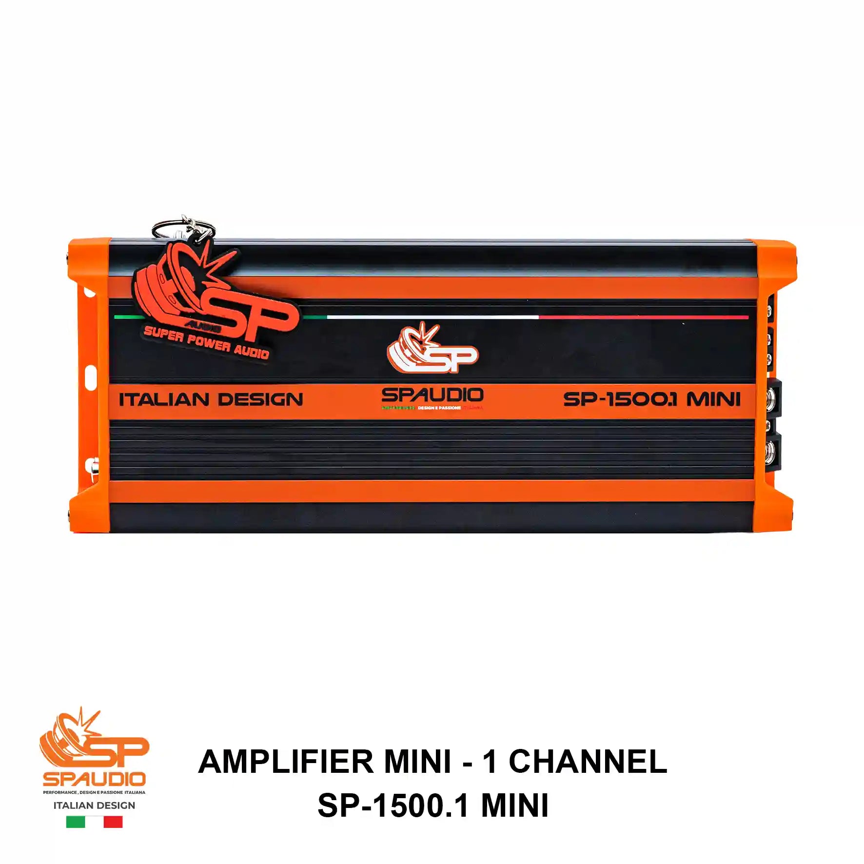
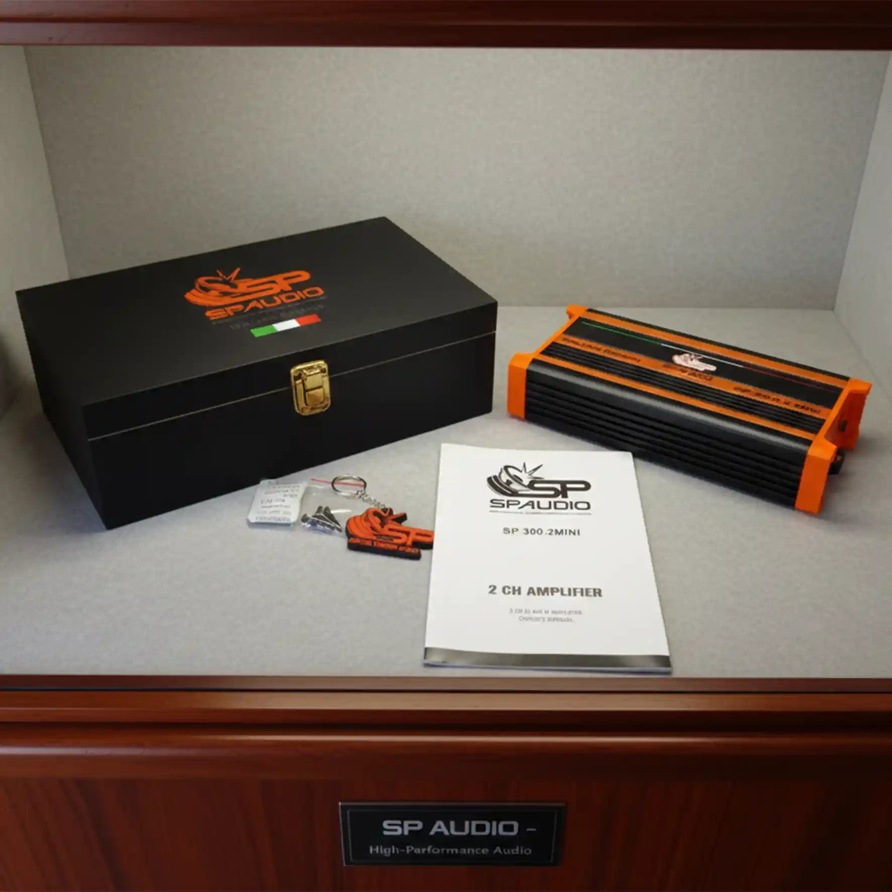
FIGURE 2: COMPLETE PACKAGE LAYOUT
AMPLIFIER MINI-1 CHANNEL SP-1500.1 MINI PREMIUM COLLECTOR'S WOODEN BOX, REMOTE BASS KNOB (EBC), CUSTOM KEYCHAIN & MOUNTING HARDWARE
TECHNICAL NOTE FROM THE SPAUDIO ACOUSTIC ENGINEERING TEAM
"When developing the MINI series, our mandate was to eliminate the old trade-off where massive sub-bass required half-meter-long amplifiers. By implementing ultra-low $R_{DS(on)}$ power MOSFETs and high-magnetic-flux toroidal transformers, we condensed 1500 True RMS Watts @ 1 Ohm into an extruded aluminum chassis measuring just 270 mm in length. This delivers an extraordinary Damping Factor that maintains absolute pneumatic and electrical control over high-excursion subwoofer cones, producing tight, authoritative, and lightning-fast bass transients."
2. MANDATORY SAFETY & PRE-INSTALLATION GUIDELINES
Installing a high-current audio amplifier requires professional competence and adherence to electrical safety standards. Any deviation from these instructions may cause severe damage to the amplifier, speakers, and the vehicle's electrical system. Damage caused by improper installation is NOT covered under warranty.
-
Disconnect Vehicle Battery: Always disconnect the negative (-) terminal of the vehicle's battery before commencing any wiring or mechanical installation to prevent accidental short circuits, electrical arcs, or equipment damage.
-
Power Cable Gauge Requirements: This amplifier draws up to 120A peak current (protected by 4 x 30A internal fuses). You must use 100% Oxygen-Free Copper (OFC) power and ground cables with a minimum cross-section of 4 AWG (approx. 21 mm²). Using undersized wiring or Copper-Clad Aluminum (CCA) causes severe voltage drops, cable overheating, and premature clipping.
-
Inline Main Fuse Protection: Install an external main fuse holder equipped with a 120A-150A fuse on the positive (+12V) power cable within 20 cm (8 inches) of the battery post. This vital protection safeguards your vehicle against catastrophic electrical fires in the event of a chassis short circuit.
-
Flawless Chassis Grounding: The ground cable (GND) must be identical in gauge to the power cable (4 AWG) and kept as short as possible (maximum 1 meter / 3 feet). Attach directly to a solid structural member of the vehicle chassis. Scrape away all paint, primer, rust, or grease until bare, shiny metal is exposed. Use a star washer and a tightly torqued bolt.
-
Thermal Dissipation & Airflow: Leave at least 5 cm (2 inches) of clearance around the extruded aluminum heatsink to facilitate natural convective cooling. Never mount the amplifier upside down, under carpets, or inside sealed, unventilated compartments.
3. PANEL ANATOMY & PARAMETRIC CONTROL FUNCTIONS
The input controls and high-current power terminals of the SP-1500.1 MINI are logically segregated on opposite sides of the chassis. This physical separation prevents high-amperage electromagnetic fields from contaminating sensitive pre-amplifier audio signals.
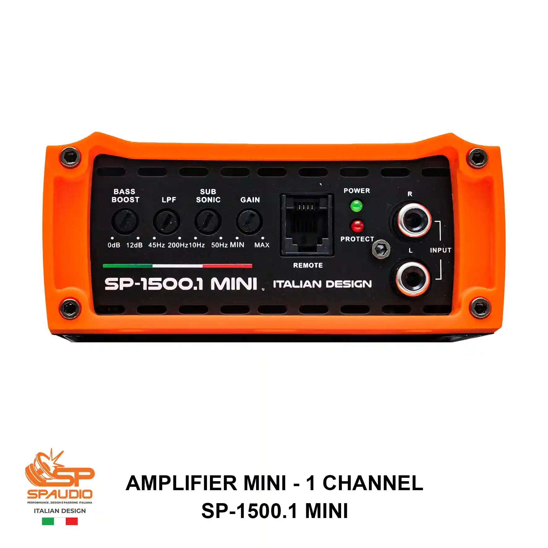
FIGURE 3: FRONT PANEL
AMPLIFIER MINI-1 CHANNEL SP-1500.1 MINI PRECISION AUDIO PROCESSING CONTROLS, REMOTE RJ-11 PORT, DIAGNOSTIC LEDS & LOW-LEVEL RCA INPUTS
| CONTROL/INTERFACE | ENGINEERING FUNCTION & CALIBRATION GUIDELINES |
|
BASS BOOST (0dB-12dB)
|
Parametric equalization circuit centered at 45 Hz. Allows acoustic boost of sub-bass frequencies up to +12dB. Caution: Use sparingly. Excessive boost causes amplifier clipping and voice coil thermal overload. |
|
LPF (45Hz-250Hz)
|
Low Pass Filter (12dB/octave slope). Blocks mid and high frequencies, allowing only clean sub-bass to reach the subwoofer. For most Sound Quality (SQ) and SPL setups, the optimal crossover setting is between 60 Hz and 80 Hz. |
|
SUB SONIC (10Hz - 50Hz)
|
Infrasonic High Pass Filter (12dB/octave slope). Essential for vented (ported) enclosures. Must be adjusted approx. 3-5 Hz below the enclosure's tuning frequency ($F_{b}$) to prevent unloading, mechanical over-excursion, and cone destruction at ultra-low frequencies. |
|
GAIN (MIN - MAX/6V-0.2V)
|
Input Sensitivity Matching Control. This is NOT a volume knob! It matches the internal preamp sensitivity to the output voltage of your head unit or DSP. Operating range spans from 200 mV (MAX sensitivity) to 6.0 Volts (MIN sensitivity). |
|
REMOTE PORT (RJ-11)
|
Dedicated modular port for connecting the included External Bass Control (EBC) knob. Enables precise driver-seat adjustment of sub-bass output level according to music genre or driving conditions. |
|
POWER/PROTECT LEDS
|
POWER (GREEN) Amplifier is powered on and operating within normal electrical and thermal parameters. PROTECT (RED) Safety protection circuit engaged due to: Speaker output short circuit, thermal overload (>85°C/185°F), severe under/over-voltage (<9V or >16V), or illegal impedance load (<1Ω). |
|
RCA INPUTS (L/R)
|
Low-level pre-amplifier signal inputs. Connect to head unit RCA outputs using shielded, twisted-pair audiophile cables to reject radiated alternator whine and electrical noise. |
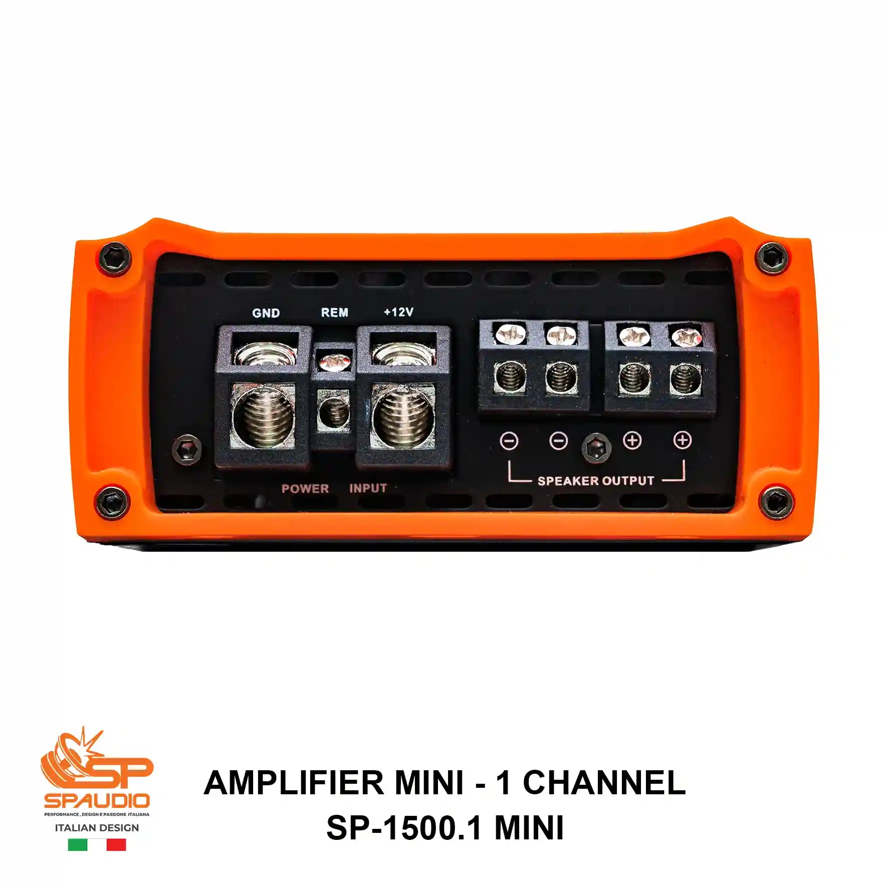
FIGURE 4: REAR PANEL
AMPLIFIER MINI-1 CHANNEL SP-1500.1 MINI HEAVY-DUTY DIRECT-INSERT POWER/GROUND BLOCKS & PARALLELED MONOBLOCK SPEAKER OUTPUT TERMINALS
| TERMINAL BLOCK | MECHANICAL & ELECTRICAL SPECIFICATIONS |
|
GND (Chassis Ground)
|
Direct-insert power terminal. Must be wired with 4 AWG (21 mm²) OFC cable directly to bare chassis metal. A high-resistance ground connection is the primary cause of amplifier overheating and voltage drop. |
|
REM (Remote Turn-On)
|
Remote turn-on trigger terminal. Connect to the "Remote Out" or "Power Antenna" lead (+12V switched) of the head unit. Synchronizes amplifier power state with your audio system. |
|
+12V (Main Power)
|
Heavy-duty direct-insert positive power input for cables up to 4 AWG. Connect directly to vehicle battery positive terminal with a 120A-150A inline fuse located within 20 cm of the battery. Torque hex screws firmly to prevent arcing. |
|
SPEAKER OUTPUTS (+/-)
|
Monoblock Speaker Output Block with Internal Paralleled Terminals. Although four terminal screws are provided (two positive and two negative), this is a 1-Channel Monoblock amplifier. Both positive terminals are wired in parallel internally on the PCB, as are both negative terminals. This dual-terminal design simplifies physical wiring of multiple subwoofers or Dual Voice Coil (DVC) configurations. |
4. MECHANICAL DIMENSIONS & ENGINEERING FOOTPRINT
The SP-1500.1 MINI is engineered to solve spatial constraints in modern vehicles without sacrificing acoustic performance. Its compact profile allows hidden installations in tight cabin spaces while maintaining exceptional structural rigidity and thermal dissipation.
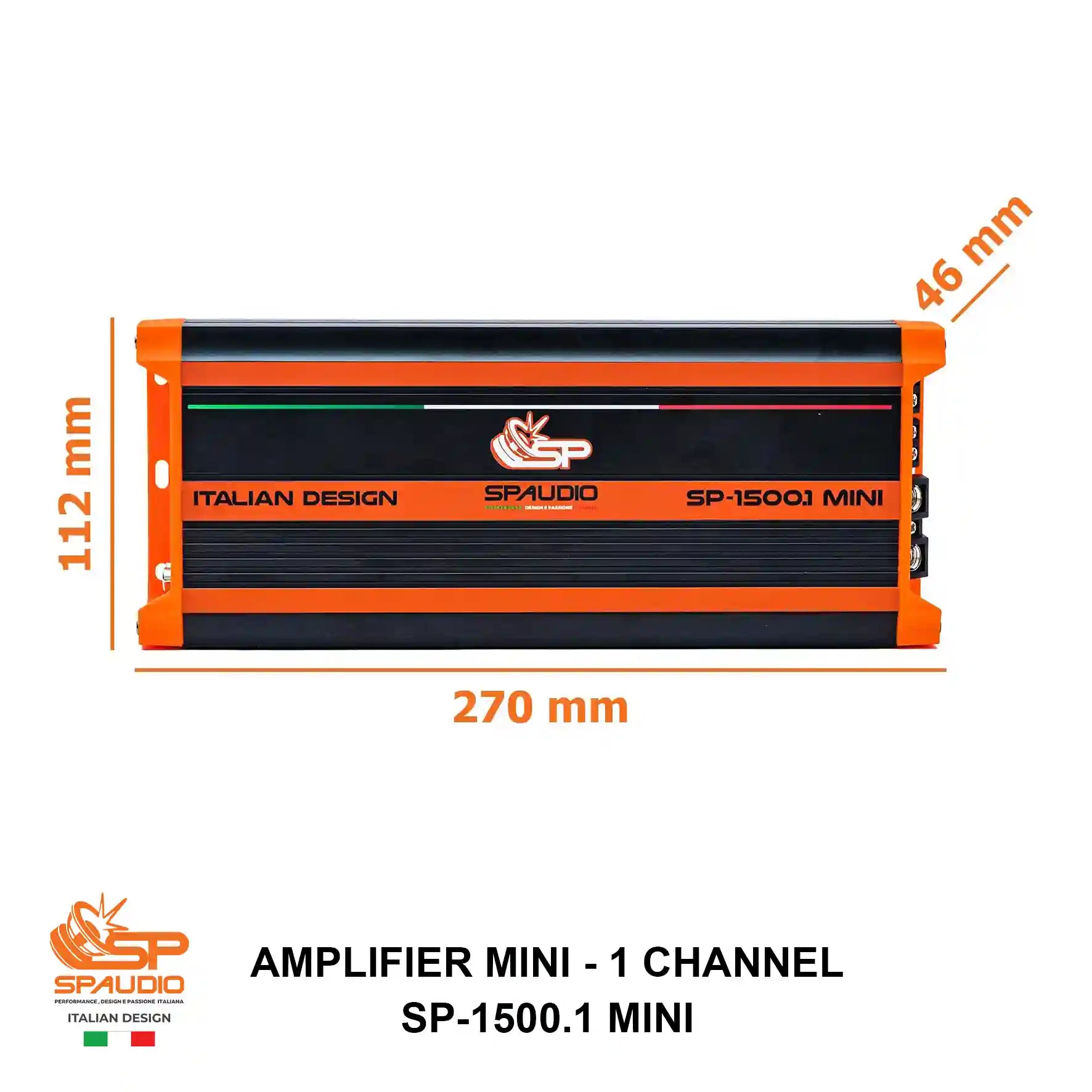
FIGURE 5: EXACT PHYSICAL DIMENSIONS
AMPLIFIER MINI-1 CHANNEL SP-1500.1 MINI LENGTH: 270 MM (10.63 IN) | WIDTH: 112 MM (4.41 IN) | HEIGHT: 46 MM (1.81 IN)
5. SYSTEM WIRING SCHEMATICS & SUBWOOFER LOAD CONFIGURATION
The SP-1500.1 MINI monoblock amplifier is fully stable down to a minimum impedance load of 1 Ohm (1Ω). Always verify total combined subwoofer impedance before powering on the system. Operating below 1 Ohm will trigger immediate current protection or permanently damage the output MOSFET stage.
FIGURE 6: COMPLETE VEHICLE ELECTRICAL & AUDIO SYSTEM ARCHITECTURE DIAGRAM
DVC 2Ω PARALLEL WIRING = 1Ω LOAD (1500W RMS)
To unleash the full 1500W RMS power of your SP-1500.1 MINI, use a subwoofer with Dual 2 Ohm Voice Coils (DVC 2Ω). By connecting both positive terminals together (+ to +) and both negative terminals together (- to -), the combined impedance seen by the amplifier is:
At 1 Ohm, the Class D output stage delivers maximum acoustic authority and extreme SPL output with complete electromagnetic stability.
DVC 4Ω PARALLEL WIRING = 2Ω LOAD (1000W RMS)
When wiring a subwoofer equipped with Dual 4 Ohm Voice Coils (DVC 4Ω) in parallel, or when wiring two single 4 Ohm (SVC 4Ω) subwoofers in parallel to the amplifier speaker terminals, the total operational impedance is:
At 2 Ohms, the amplifier generates an impressive 1000 Watt RMS, yielding ultra-cool thermal operation and an elevated Damping Factor for audiophile SQ sound reproduction.
6. SCIENTIFIC GAIN CALIBRATION & CROSSOVER SETUP PROCEDURE
Calibrating the GAIN potentiometer is the most critical stage of audio installation. Setting the Gain too high does not increase maximum power; it saturates the input stage, forcing the amplifier into square-wave clipping. Clipped signals produce massive thermal harmonics that melt subwoofer voice coils within seconds.
PRECISION CALIBRATION PROTOCOL (USING DIGITAL MULTIMETER OR OSCILLOSCOPE)
-
Disconnect Subwoofer: For safety during calibration, physically disconnect speaker cables from the amplifier's speaker output terminals.
-
Zero All Processing: Turn the GAIN control completely counter-clockwise to the MIN position (6.0V sensitivity). Set Bass Boost to 0 dB. Set LPF to 80 Hz and Subsonic to 25 Hz.
-
Configure Head Unit: Turn on your head unit. Disable all EQ presets, loudness, and bass boost features. Set head unit volume to exactly 75% of maximum clean volume (e.g., volume level 30 out of 40). This represents the maximum unclipped preamp output voltage.
-
Play Test Tone: Play a clean 50 Hz or 40 Hz sine wave test tone recorded at 0 dBFS on continuous loop via USB or lossless media.
-
Calculate Target Voltage ($V_{target}$): Determine the required AC output voltage for your rated power and speaker impedance using Ohm's Law:
$$V_{target}=\sqrt{P_{RMS}\times Z_{load}}$$Example for 1 Ohm Load @ 1500W RMS: $V_{target}=\sqrt{1500\times1}=\sqrt{1500}=38.73$ Volts AC. Example for 2 Ohm Load @ 1000W RMS: $V_{target}=\sqrt{1000\times2}=\sqrt{2000}=44.72$ Volts AC.
-
Adjust Gain Control: Set your digital multimeter to AC Voltage (V AC) and touch the probes to the amplifier's speaker output terminals (+ and -). Slowly rotate the GAIN potentiometer clockwise until the multimeter display reads exactly the calculated target voltage (e.g., 38.7 V AC). If using an oscilloscope, stop immediately before the sine wave peaks begin to flatten or clip.
-
Reconnect Subwoofer: Lower head unit volume to zero, power down the audio system, and securely reconnect subwoofer speaker cables. Your SP-1500.1 MINI is now calibrated for maximum clean, unclipped acoustic output.
7. CERTIFIED TECHNICAL SPECIFICATIONS
All electrical and acoustic parameters are laboratory tested and verified using industry-standard Audio Precision testing equipment at 14.4V DC reference battery voltage and 25°C ambient temperature.
| ELECTRICAL/ACOUSTIC PARAMETER | CERTIFIED VALUE - SPAUDIO SP-1500.1 MINI |
|
RMS Power @ 4 Ohm (≤1% THD+N)
|
600 W x 1 CH |
|
RMS Power @ 2 Ohm (≤ 1% THD+N)
|
1000 W x 1 CH |
|
RMS Power @ 1 Ohm (≤ 1% THD+N)
|
1500 W x 1 CH (Optimal SPL Output) |
|
Frequency Response (-3dB)
|
10 Hz - 200 Hz |
|
Signal-to-Noise Ratio (S/N Ratio)
|
≥90 dB (A-Weighted Clean Signal) |
|
Total Harmonic Distortion (THD+N)
|
<0.1% @ 100 Hz / 4 Ohm |
|
Input Sensitivity Range (Line Level)
|
200 mV - 6.0 V (Continuously Variable) |
|
Low Pass Filter (LPF Crossover)
|
45 Hz - 250 Hz (12 dB/Octave Butterworth Slope) |
|
Subsonic Filter (Infrasonic Protection)
|
10 Hz (OFF) - 50 Hz (12 dB/Octave Slope) |
|
Parametric Bass Boost
|
0 dB - +12 dB (Centered at 45 Hz) |
|
Operating Voltage Range
|
9.0 V - 16.0 V DC (Negative Ground) |
|
Internal Fuse Rating
|
30A x 4 (120A Peak Current Demand) |
|
Physical Dimensions (L x W x H)
|
270 mm x 112 mm x 46 mm (10.63" x 4.41" x 1.81") |
|
PCB Architecture & Components
|
Military-Spec SMD Components on 2-Layer FR-4 Fiberglass PCB |
|
Multi-Stage Safety Protections
|
Thermal (>85°C), Output Short Circuit, Over-Voltage, Under-Voltage, DC Offset |
8. DIAGNOSTICS, TROUBLESHOOTING & WARRANTY POLICY
If your amplifier experiences operational anomalies, consult the following engineering diagnostic matrix before contacting your authorized Spaudio dealer or technical support.
| SYMPTOM IDENTIFIED | PROBABLE ENGINEERING CAUSE | RECOMMENDED DIAGNOSTIC ACTION |
|
No Power / Won't Turn On (Both LEDS OFF)
|
1. Missing +12V main power or REM voltage. 2. Blown main inline fuse or internal fuses. 3. Bad or oxidized chassis ground (GND). |
Use a multimeter to verify at least +12.0V DC across +12V and GND terminals, and +12.0V at REM terminal when head unit is ON. Inspect external fuse under hood. Unbolt GND wire, scrape chassis metal to bare steel, and retorque securely. |
|
PROTECT LED ON (Red) (Safety Shutdown)
|
1. Speaker wires shorted together or to chassis. 2. Subwoofer impedance below 1 Ohm limit. 3. Amplifier overheating (>85°C / 185°F). 4. Battery voltage abnormal (<9V or >16V). |
Disconnect speaker cables immediately. If Red LED goes out, check subwoofer wiring with multimeter for shorts or illegal load (<1Ω). If heatsink is hot to the touch, allow amplifier to cool down and improve cabin airflow around unit. |
|
Distorted Audio or Weak Bass Output
|
1. GAIN sensitivity calibrated incorrectly. 2. Battery voltage dropping under heavy bass. 3. Subwoofer voice coil partially damaged/burnt. |
Recalibrate GAIN using Section 6 scientific protocol with 50 Hz test tone and multimeter. Measure voltage at amplifier terminals with engine running during bass hits; voltage must not drop below 12.0V. Check electrical charging system. |
|
High-Pitched Whine / Alternator Noise
|
1. Ground loop in vehicle audio wiring. 2. RCA cables run parallel to +12V power cables. 3. Broken RCA shield or faulty head unit ground. |
Physically separate RCA signal cables from high-current +12V power cables by at least 30 cm (12 inches). Ground head unit chassis directly to the same grounding point as the amplifier. Test with high-grade shielded RCA cables. |
SPAUDIO OFFICIAL WARRANTY & TECHNICAL SUPPORT POLICY
All Spaudio high-performance audio components are engineered, rigorously manufactured, and quality-tested to meet uncompromising standards of acoustic perfection. The SP-1500.1 MINI is backed by an official manufacturer's warranty against defects in materials and craftsmanship in accordance with local statutory regulations in the country of purchase.
Important Warranty Terms: Please retain your original dated sales receipt or invoice from an authorized Spaudio retailer. Warranty coverage becomes void in the event of unauthorized chassis opening, modification, thermal/electrical overload from improper wiring or clipping, abuse, or operating the amplifier in competition environments outside certified engineering parameters.